Thanks to Covid-19, everything is in a bit of a limbo at the moment. We started planning for a new train room, but that had to be put on hold due to impacted finances. At the same token, because of that planning, we are not making any major changes to the current layout – it’s only still up so the trains can run once in a while. We need the room it is currently in, so as soon as we can resume the work on the new train room, this one will be dismantled. A new train project had to be put on hold for a similar reason.
But recently I had the itch to do something anyway, something new. I started to experiment with sensors and feedback, in order to automate the running of trains. The materials for this have been lying around for a while, acquired at different occasions, so I figured I might as well put them to use.
Regular feedback setups for model railway, which often integrate into bus systems such as LocoNet or XpressNet, are quite expensive. For some time I have been researching a more cost-effective option, which I believed to have in the combination of Arduino sensors, and Arduino board, and the DCC++ software, a package that turns an Arduino into a DCC command station.
The nice thing about this combination is that it works out to a really low price per sensor, compared to other solutions. A 16 channel LocoNet or S88 board can easily set you back north of 50 Euros depending on the brand. An Arduino Mega board can be had for way less than that, and it offers up to 54 digital inputs which can be used for sensors. The sensor modules are also fairly cheap. On the downside, whatever software is used for the automation needs to be compatible with DCC++, which is not always the case.
Since I already have my DR5000, I didn’t bother setting up the Arduino as an actual command station – it requires a motor shield to do that. It only needed to be able to process inputs coming from sensors, and for that, the software on a bare Arduino is good enough. The next question was which type of sensor to use. A lot of feedback systems use current detectors, which require specific wiring and insulation of track segments. Retrofitting these sensor types onto an existing layout is lots of work and not optimal. Other options include photoresistors, light barriers, infrared sensors, or reed switches.
I initially played with photoresistors – the idea being that they get tripped by trains blocking out the light when driving over them – but after the first few tests I started getting doubts about their reliability in the wildly varying lighting conditions in my train room, so I didn’t even bother putting them under the tracks.
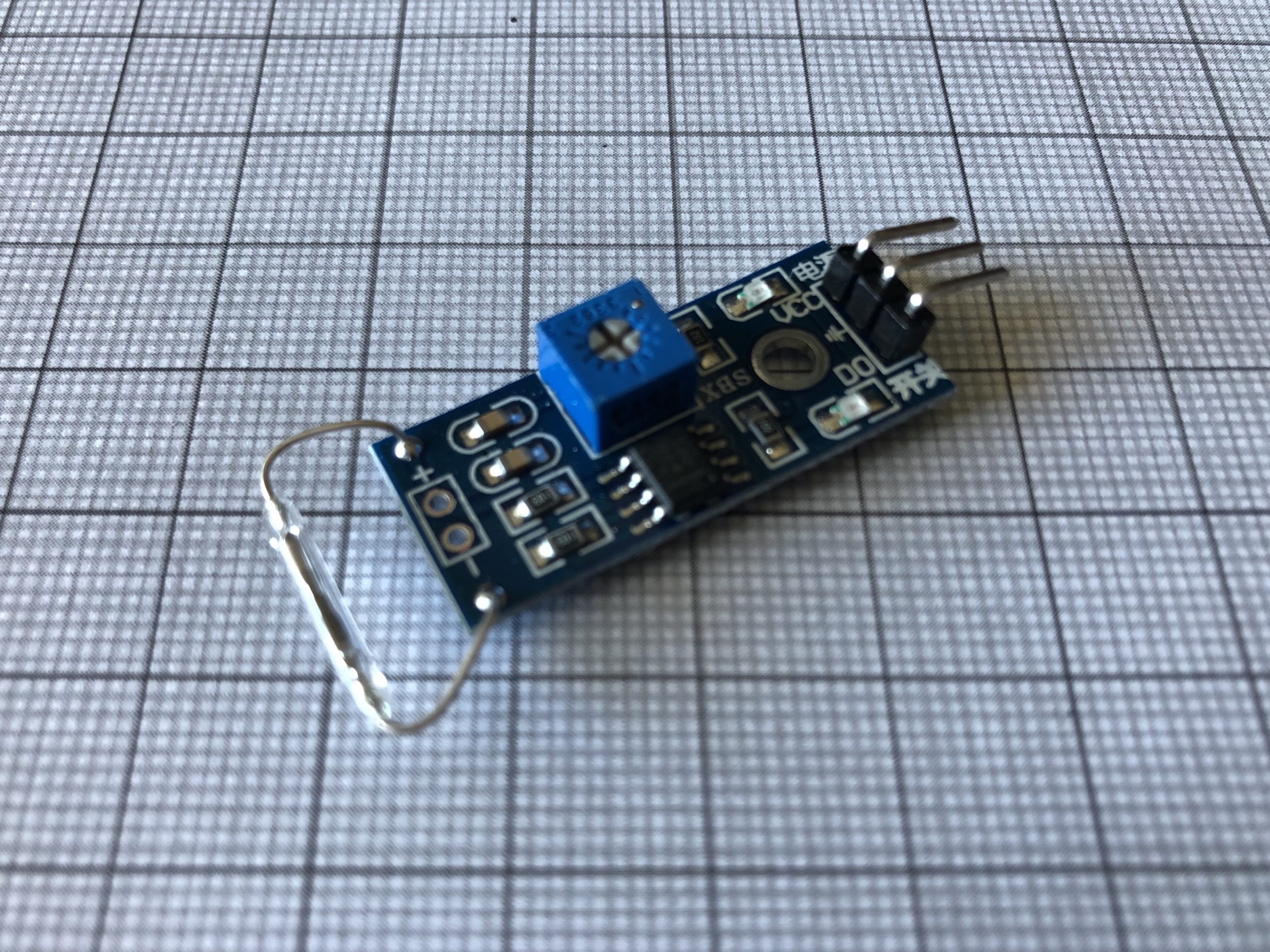
The next trials were made with reed switch modules, which are tripped by a magnetic field. I was immediately convinced by the initial results and wanted to proceed with tests on live track. As can be seen in the pictures below, the modules are not small, and would not fit under regular H0 track as they are. My workaround was to desolder the actual reed switch from the module, solder two lengths of wire onto the same contacts, feed these wires through the baseboard and then solder the reed switch back onto the wires. That worked well enough, but I learned that you have to threat the reed switches very gently – I broke two of the fragile glass tubes while doing this work.

The Arduino photosensor module used for the first tests 
The Arduino reed switch module
But once the switches were under the track, and everything was connected up, they worked. I performed the first few tests with my LINT 27 railcar, and stuck a small magnet on its underside, but soon noticed that it was tripping the sensors without the extra magnet. The next step was to set up the automation – initially I just wanted the railcar to go around its oval and stop at the station on each pass. The result can be seen in the below video. The Arduino and the two reed switch modules with the red LEDs are visible, and LEDs flash on the modules when the train triggers a sensor.
From here, it’s all in the software, and how it deals with the information provided by the sensors. How I got on with RocRail will be described in the next post of this series. Watch this space.

