Recently I found the time to start on a little project that has been going through my head for a while. I wanted to build a separate test track, in a manner of speaking, which could be easily connected to a digital central or other device, and let me program and check trains away from the main layout.
Over time, a few devices have accumulated. I have a decoder tester, and more recently, a LokProgrammer. The latter can be hooked up to a piece of track or the tester, and is used to program all aspects of ESU decoders including sound. In my previous layout, I had a piece of track set aside as the programming track, which was connected to the programming output of the DR5000. That was fairly risk-free, since that output would put regular driving voltage on the track when it was not actively programming. However, the LokProgrammer needs to be strictly insulated, receiving any voltage onto its track output could destroy it. So while perfectly possible with the right wiring, connecting it to the layout is not something I want to do.
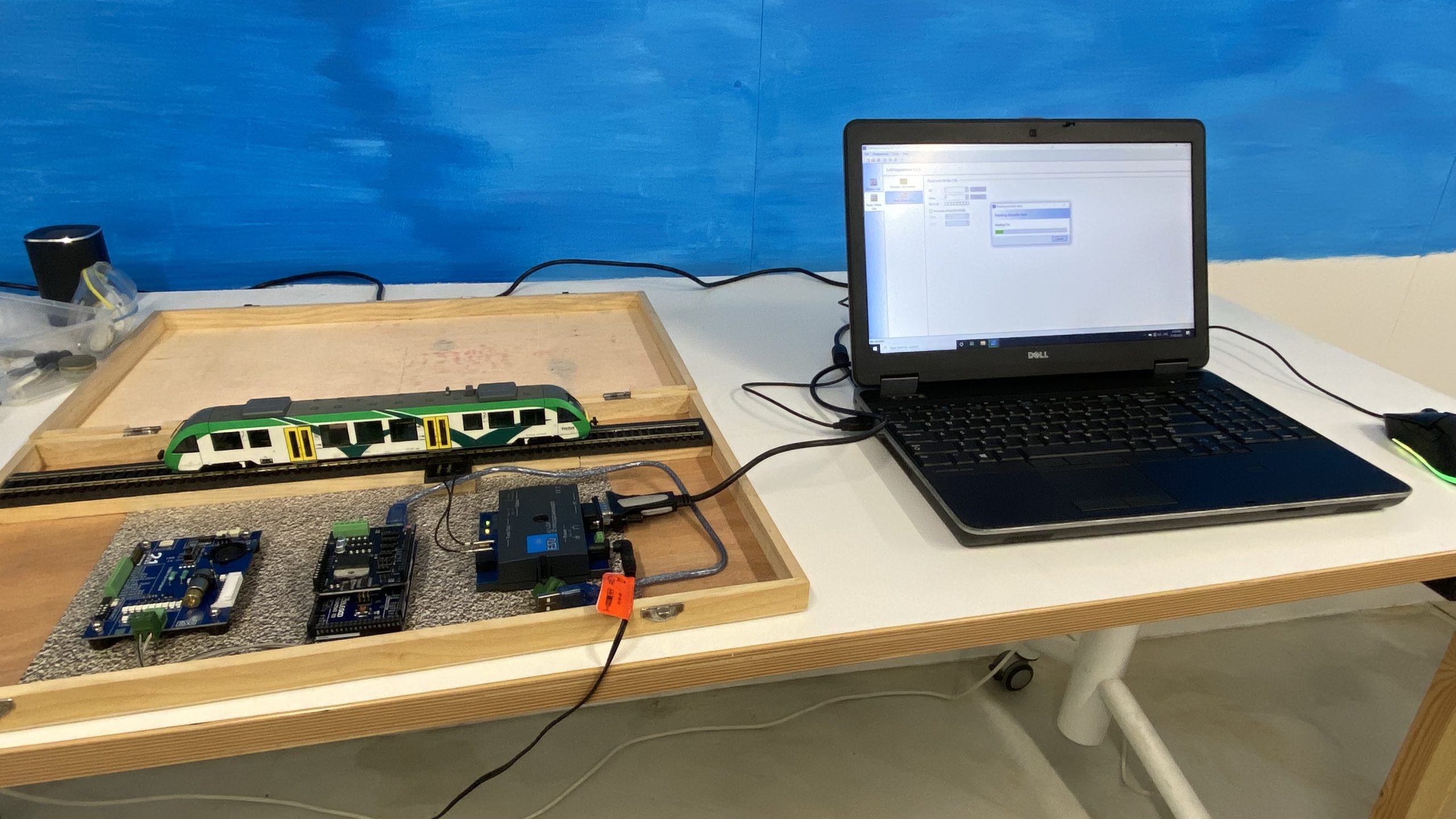
The idea of this programming box is to have a one-stop solution for any digital programming and test tasks. A train can be set onto a piece of track, or a decoder can be plugged onto the tester for initial setup. So far, so good. Since not all my decoders are or will be ESU, I needed another device to handle the cases the LokProgrammer couldn’t. That device is a real low-cost option, an Arduino-based DCC++ central.
As base for this box, I obtained an old arts supplies box, which was stripped of its former contents. Its size is roughly 50x30cm, so it can take a piece of track long enough for most trains.

A first attempt to line up the components looked a bit like this:

The lid of the box is very thin, so I can’t put any screws through it to keep the components in place. I didn’t want to do anything non-reversible, so I attached the devices with removable glue dots. Since these don’t hold very well on wood, I glued a piece of glossy cardboard into the box.
The piece of track was lifted onto some leftover timber bits, which I nailed in from the other side. This way the track itself could be nailed in and didn’t need to be glued. To connect wires to the track, I am using a track connector which takes mini banana plugs.

With this first iteration, I have to manually wire up each connection as needed. Both the LokProgrammer and the Arduino have their own USB cable. On the Arduino, the motor shield needs its own power, but I can use the same power supply as for the LokProgrammer. Then I need to connect the required device either to the track or the tester.
For the time being, this is a sufficiently usable setup. In the future, I would like to change it so I can manage the setup with switches, but that will take a bit more planning and testing.
Pingback: A Brief Update on what happened while this blog was offline – Making Tracks