Feedback Experiments, Pt. II
The next post in this series was originally going to describe how I implemented the first automation experiment in the control software I am using. But I have changed my mind on that, for two reasons. One, I have something else that I'd rather write about at this time. Two, there is a not insignificant chance that I might change to a different control software in the near future. I am already evaluating options and will see where I land, at which time I will of course report on the implementation.
In the meantime, I went back to the hardware side of things. Previously, I implemented feedback with reed sensor modules and an Arduino that ran DCC++ as a base station. That was all good and well, but I originally started these experiments when I still had my previous DCC controller, which had very restricted feedback options. I continued to play with DCC++ when I got the new central, but then a thought kept popping into my head. The DR5000 features all these well-supported bus systems - LocoNet, XpressNet, S88 - why not use one of them? The fact that DCC++ had been abandoned by the original developers kept playing into this as well (although by now there is at least one viable fork that is being actively developed).
And why not? Because, as mentioned before, the commercially available feedback modules for any of those bus systems are quite expensive. Digikeijs, the maker of my DCC central, produce LocoNet feedback modules that start at EUR60 for a 16 channel module. Other manufacturer's modules come in at similar price points. There had to be something else, something with a better bang for buck.
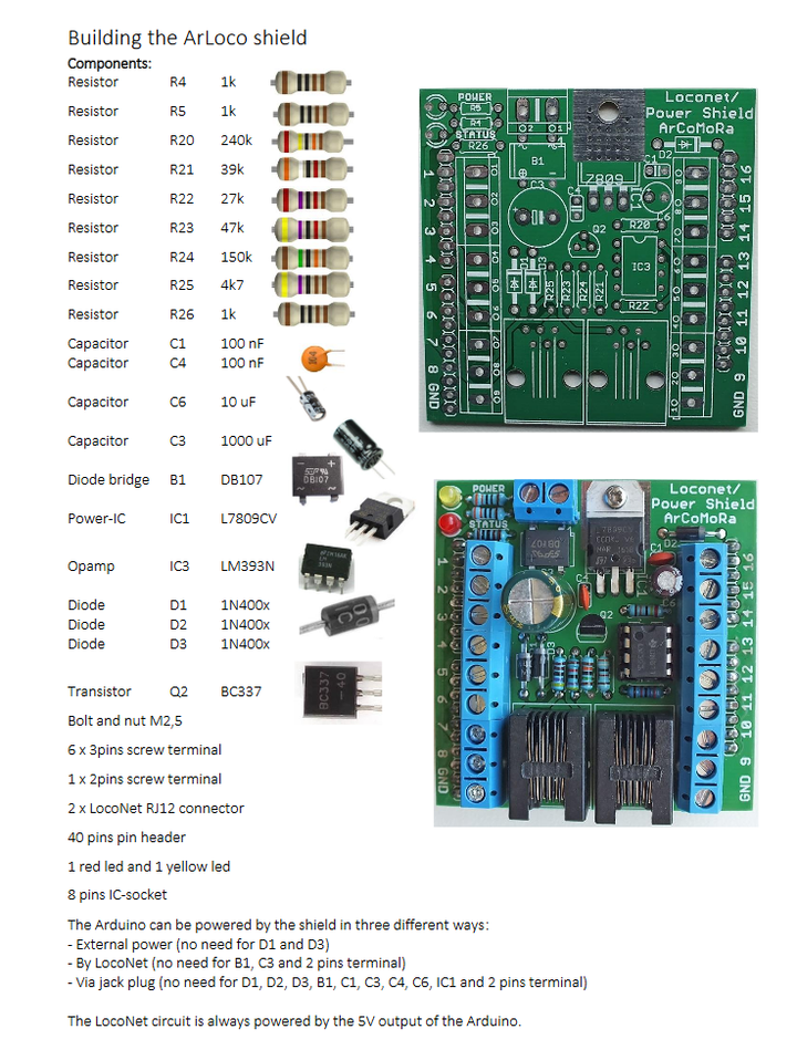
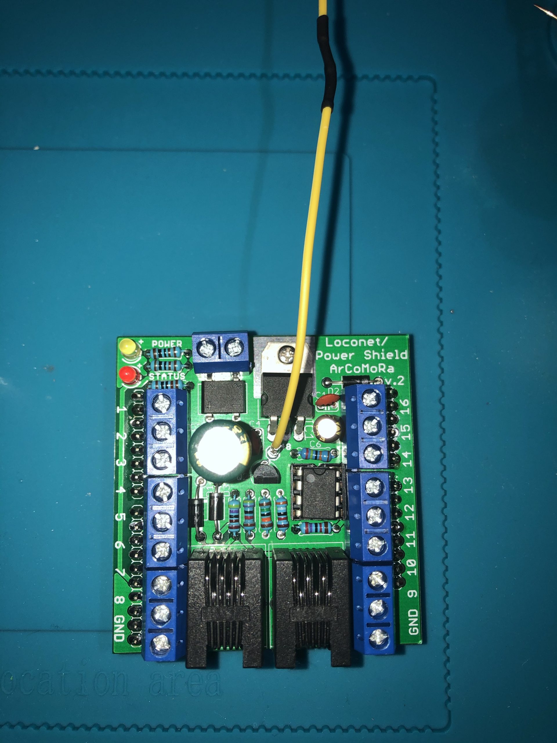
And there was. After some research, I stumbled across the ArCoMoRa project by Netherlands-based railway modeller Nico Teering. Arduino-Controlled Model Railway is a combination of software and custom hardware for Arduino, to provide accessory control, lighting control, and feedback, with a low budget. Nico provides the software for free, and sells the PCBs and components for the Arduino shields basically at cost price. One of the solutions is the ArLoco, an Arduino shield for LocoNet feedback. I ordered two of them - since I already had the Arduino - and finally put them together in the past few weeks.
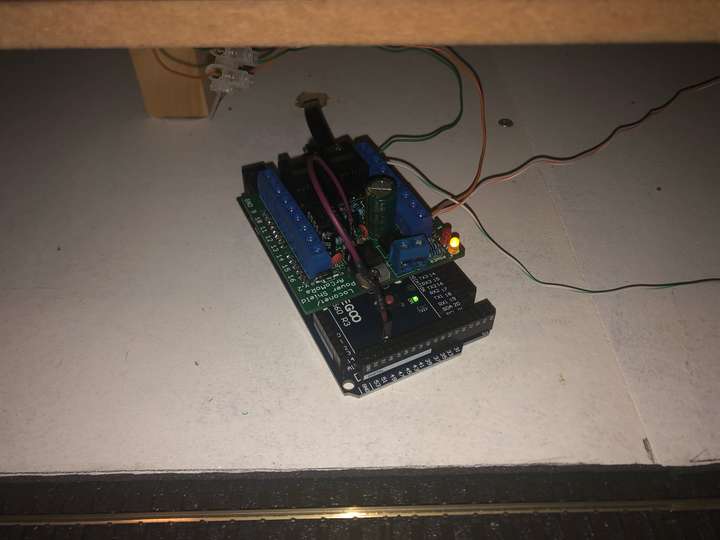
The ArLoco is intended for the Arduino Uno, on which it provides the usual 16 feedback channels. Consider that a usable Arduino clone can be had for a few bucks, and the ArLoco doesn't cost that much more, plus the time to assemble, you're already at a fraction of a commercial module. But here's the beauty: the ArLoco can also be put on an Arduino Mega, and then you have a whopping 58 feedback channels, for only a little more money. My Arduino happened to be a Mega, so I was especially happy with that proposition.
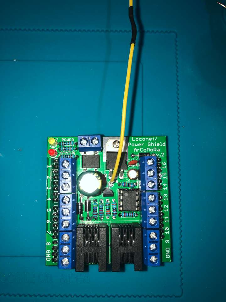
Assembling the ArLoco requires soldering, but it is dead-easy, thanks to an exemplary manual, and a printed PCB which leaves absolutely no doubt about which component goes where, and if applicable, which way round. Nico provides the PCB and all other required components - ICs, resistors, capacitors, connectors etc., so all you have to do is follow the instructions and be a bit handy with the soldering iron. The most difficult bit is probably to keep the resistors apart and make sure they go in the right spot - there are seven different resistor types and nine resistors in total. As a relative soldering beginner, it took me about 1 1/2 hours to put together the first ArLoco, and it worked on first try.
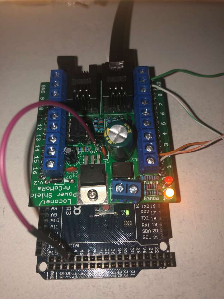
Well, not exactly. I learned the hard way that it pays to follow instructions as written, and not make assumptions. The pinout on the Arduino Mega is slightly different from an Uno, so the PCB provides a special contact which has to be connected with Pin 48 on the Mega - with an Uno that contact stays unused. I did not do that initially, and wondered why the ArLoco seemed to work as far as the software was concerned, but my command station did not pick up any signals from the module. Once the extra connection was made, everything worked beautifully. I assembled the second ArLoco in a similar time frame, tested and found it working as well as the first.
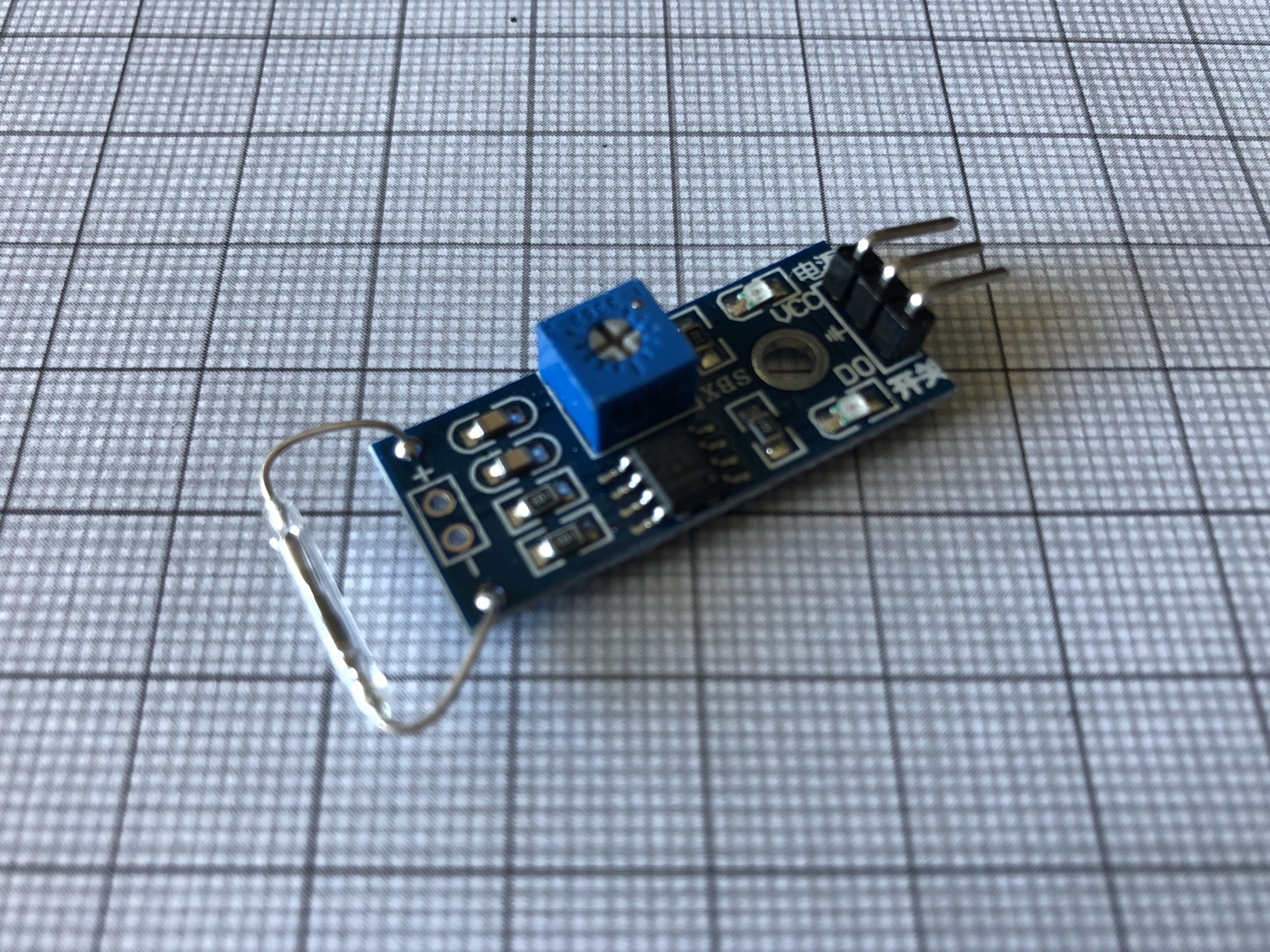
A small change was required for the sensors themselves. The ArLoco works with reed switches with two contacts, but not with the pre-assembled Arduino reed switch modules I was using, which have three contacts (voltage, ground, and digital signal). Since I had already unsoldered the actual reed switches from the modules to add a length of wire in between, it was easy enough to make the change - I simply cut off the modules and connected the two legs of the reed switches directly to the ArLoco.
This did not change anything in the automation I created in my software - all I had to do there was change the sensor addresses. The railcar still drives around the oval and stops at the station each time. That's not the most exciting thing to do with this kind of automation, but it served its purpose, which was for me to learn and understand such automation with a simple practical example.
