Layout Progress
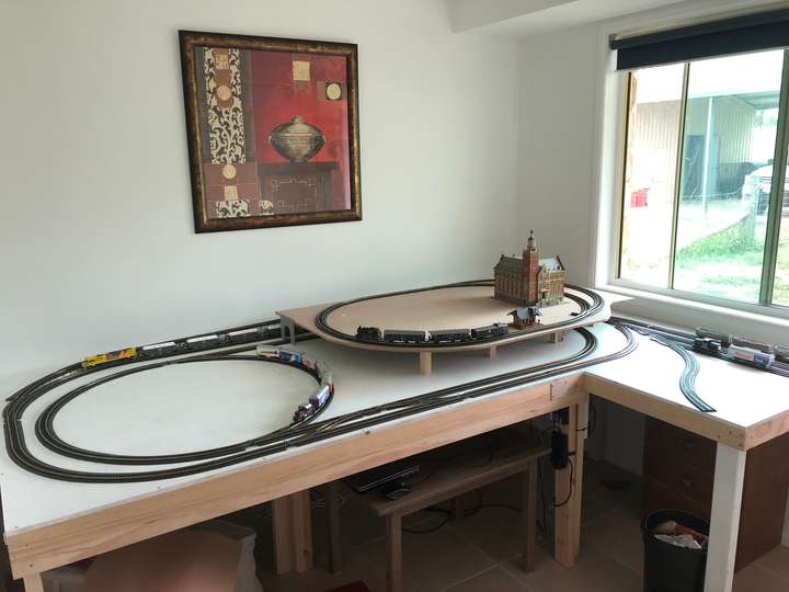
A while ago I posted the track plan, which itself had taken some time to finalise. At the time, building the layout was a work in progress. The bottom layer was completed without too many difficulties, but the top section posed some challenges.
There was some initial delay beginning the work on the top section to start with, mainly due to some uncertainty about the tracks that were to be covered - issues like dirty track that might hamper trains going below the covered parts, as well as rolling stock not reliably crossing turnouts, with the s-curve going into the long siding on the Eastern side being a particular issue.
While these issues are not yet fully under control, over time their root causes became sufficiently known and mitigated to the point where there was no reason to further delay the construction of the top section.
It was always clear that the table itself had to be movable. So far, this was accomplished by joining the two original sections with bolts and wingnuts. The wiring below the table is also detachable, joined with terminal blocks. All tracks have joints right above the table joints. However, the top section would extend over both parts of the table, so we had to come up with something new there.
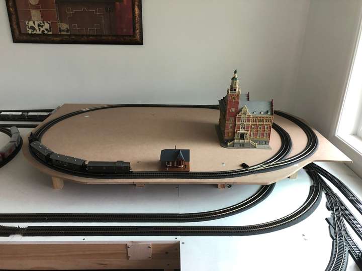
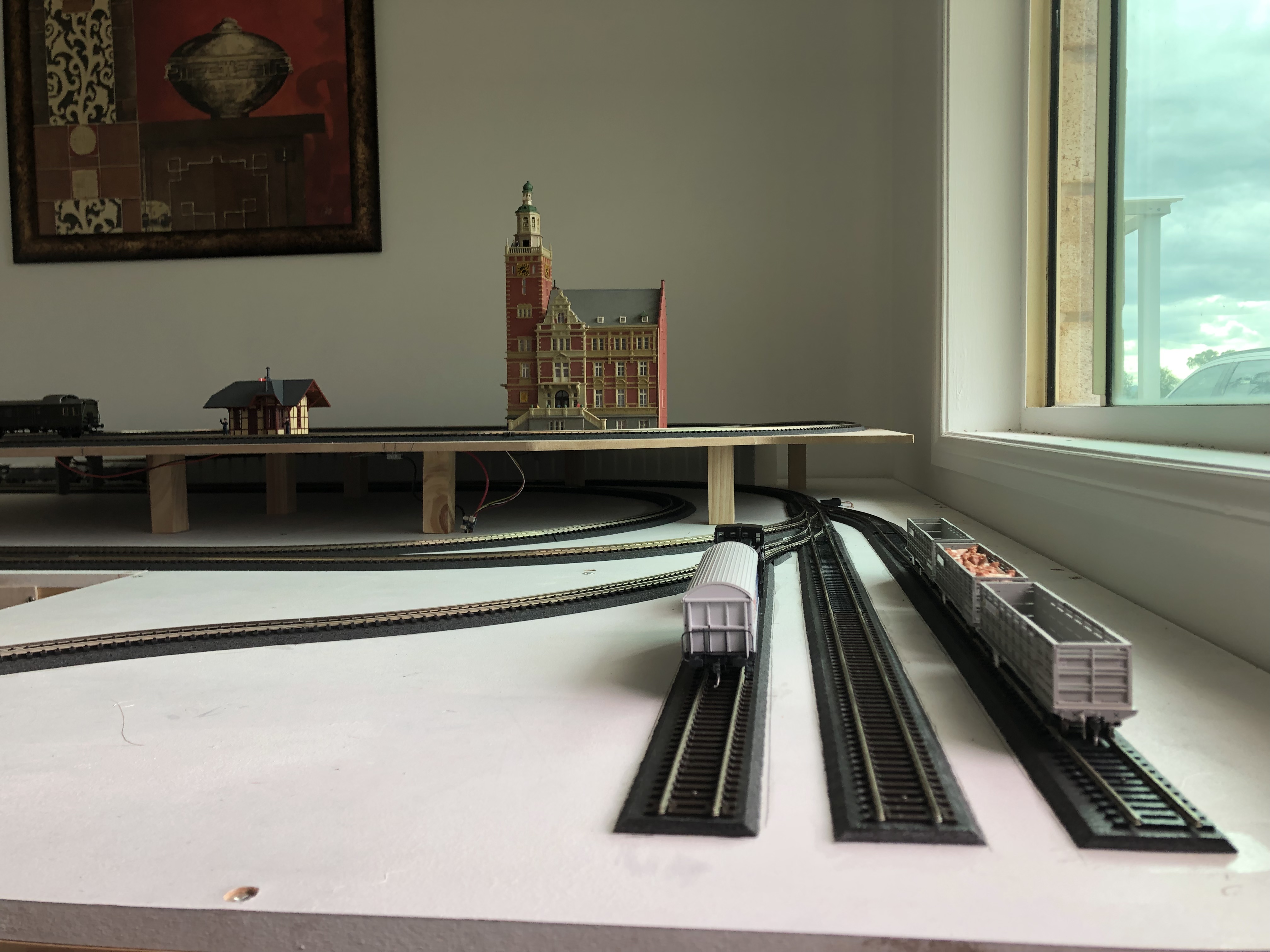
We had originally tried to create the top from several, smaller pieces, but that proved to be suboptimal. So in the end, it was constructed from a single piece of 9mm MDF and put on small legs, which had to be cut as evenly as possible to make the section level. Initially those legs were attached to the top section itself, but that was not a good way to do things.
Most of the edges were cut free-hand, and it took several attempts to make it fit properly. During this fitting process, the entire assembly was removed from the layout several times. The first time I tried to re-fit it - with attached legs - I ripped up half the yard. After that, I decided to attach the legs to the bottom level, and simply slide the top onto them. That worked a lot better than expected.
The section remains removable. It is fixed in place onto two of the legs with screws - mainly to make sure it can be properly realigned after removing it. The wiring is, again, joined with terminal blocks. The single point motor used on the top section has an extension cable with a plug. Once all those connections are separated, the section will simply slide off. This will pose some challenges in the future with regards to buildings and landscaping, but probably nothing that we can't figure out.
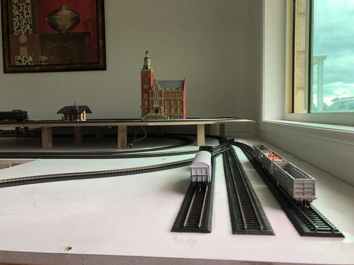
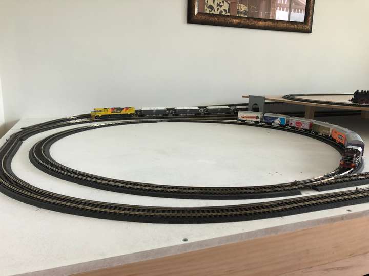
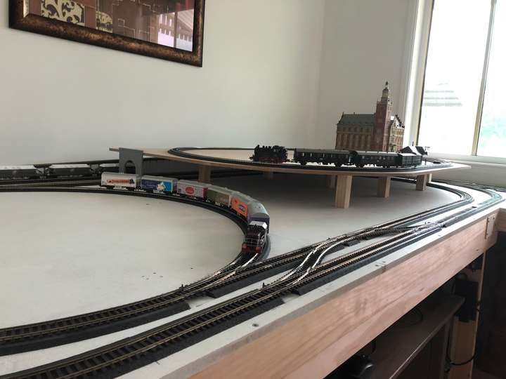
The photos below show where we are at. Trains can currently travel everywhere, and all of my locos can handle the 4% incline from the bottom to the top, which is sitting at the far back.
What's next? Landscaping and buildings. As the pictures show, there are already some buildings on the layout - the big one being a model of a German town hall which we 'inherited' from my mother-in law. We didn't know if it was the correct scale, but it looked good enough, so we got it (and have since found out that it is, in fact, the correct scale, and still being sold as a building kit). We're still tossing around some ideas on what exactly we are going to do with the individual sections, but we're getting closer to the final visions. As always, watch this space.
