Project Pendolino, Part I: Let's get it moving, shall we?
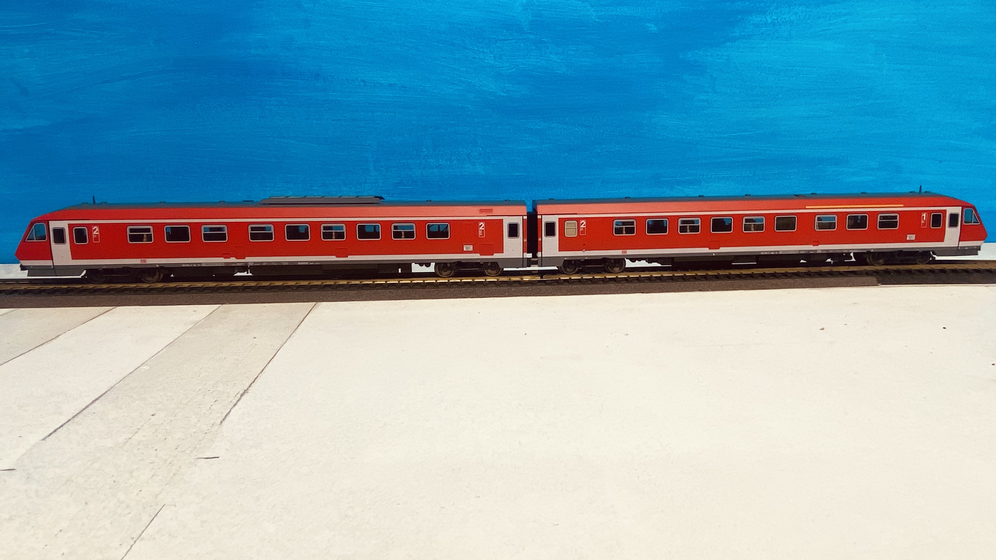
This Fleischmann BR 610 really is a lovely model. It looks gorgeous, is nicely detailed, the print quality is near flawless, and the idea of an actual tilting mechanic is great, even if it is not exactly prototypical. But, alas, looks aren't everything, especially when it comes to a second hand acquisition.
The first thing most railway modellers will do with a new model is put it on the track and see if/how it runs. I am no exception myself. After verifying the nature of the decoder and its configuration, on the track it went. And that didn't go overly well - though I had kind of expected this.
Fleischmann models have a reputation of being solid and long-lived. Lots of modellers love them, and they have pretty good resale value. But they also have some idiosyncrasies that may scare off less experienced modellers - they certainly made me hesitate to buy Fleischmann so far.
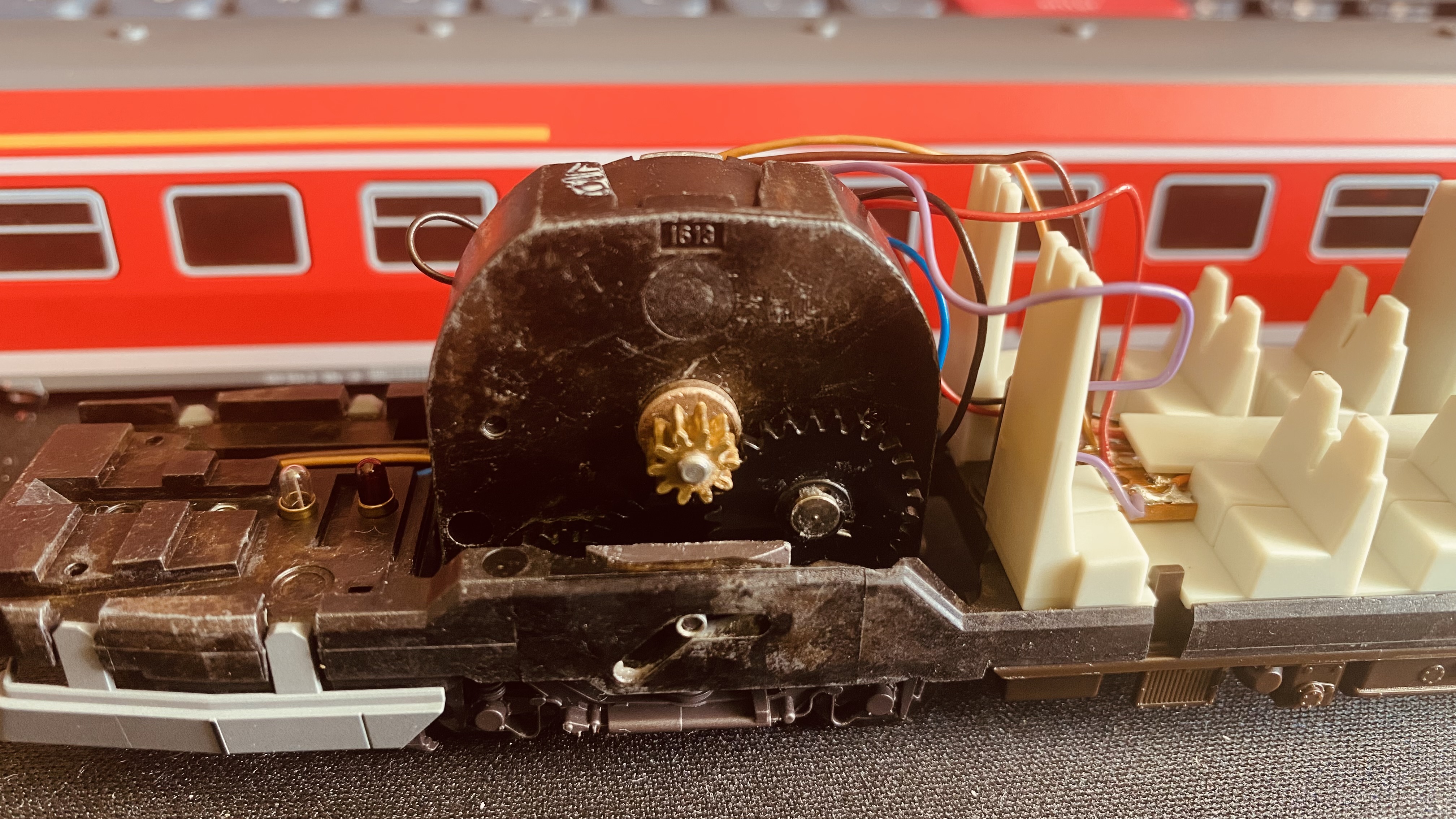
One of these characteristics is that they can be a bit problematic to digitalise. Fleischmann used a type of motor that sits upright in the model, usually driving only one bogie directly. This type is often referred to as 'pancake motor'. They are, in theory, easy to maintain because they can be fully disassembled and are not encapsulated. The motor internals are covered by a removable shield which also carries most of the wire connections. In older motors, this shield is made of metal, in newer ones it is a kind of PCB.
In many pre-digital Fleischmann models, one motor pole is directly connected to the chassis and rail. This connection has to be severed before a digital decoder is fitted, otherwise the decoder will suffer irreparable damage. Depending on the age of the motor, this can be as simple as severing a specific connection on the PCB shield. If the shield is metal, it often has to be replaced. As time goes by, spare parts are becoming harder to obtain.
Since my model is already digital, this was not a problem. However, its running characteristics were pretty poor. It appeared to struggle with power pickup and ran very haltingly on my test track. On my ECoS-driven layout, it did not move a millimetre. Also, the lights did not appear to work at all. So, it was time to take a look under the hood.
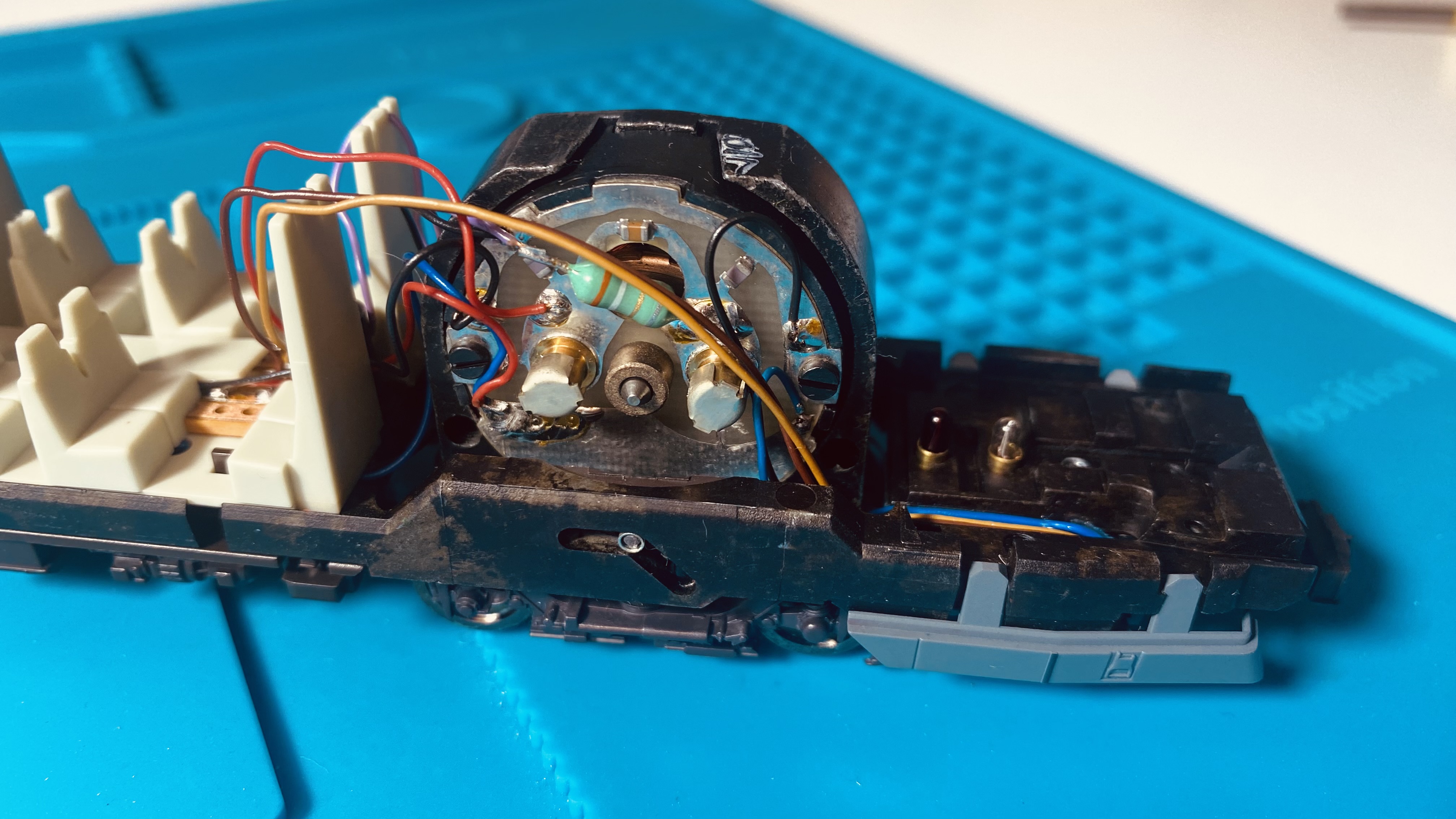
The above photo shows the motor with its removable shield. The two brass caps cover the spring loaded carbon brushes. Removing the shield is only possible after first removing the bogie from the chassis, then removing the plastic bogie cover. Once the shield is removed, the copper rotor and wire windings are visible.
The rotor and coal brushes appear to be common problem sources if not maintained for a long time, if search results on relevant forums are anything to go by. The brushes can get oily, the rotor really mucky. Both hinder the smooth running of the motor. My exemplar didn't appear to be too bad. the brushes themselves were dry, and the rotor had some dirt on it, which was cleaned off quickly. After a reassembly and some gearbox lubricant the model ran better, but still not well - it's noisy and runs haltingly. And still not a peep when it was sitting on the layout.
As a next step I cleaned all wheels and power pickups as well as I could, which again brought some improvement, but I wasn't yet satisfied. As for the other issues, some research was in order. This gave me some ideas for what to do next.
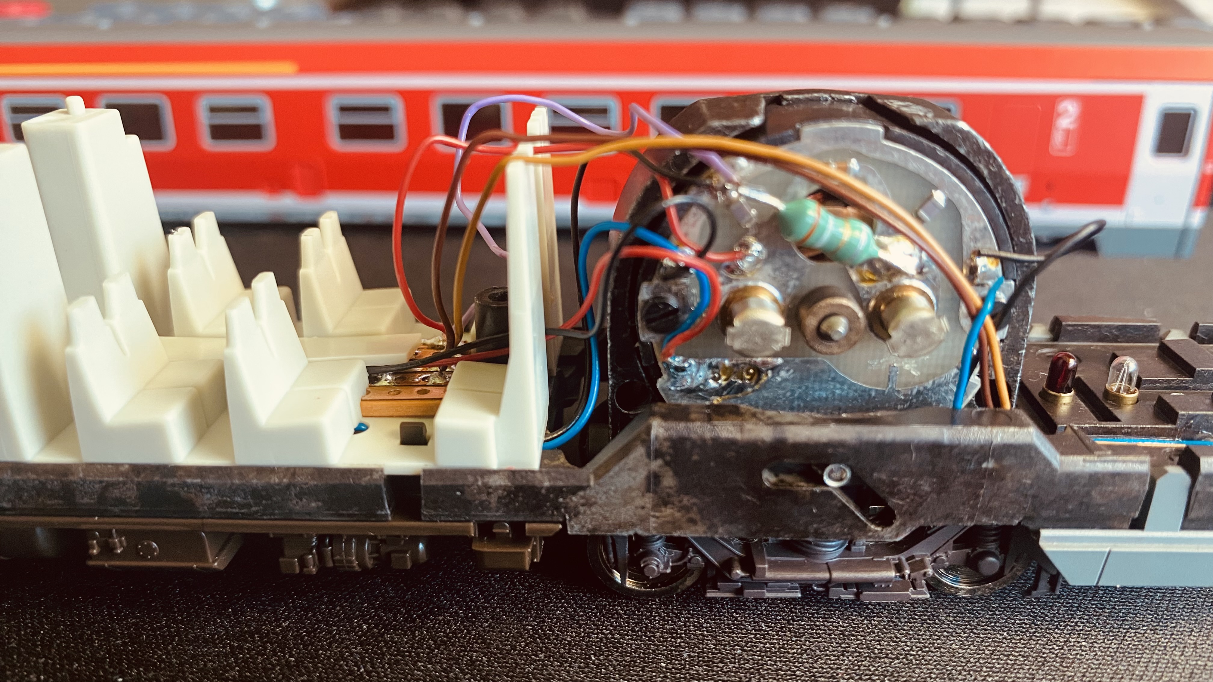
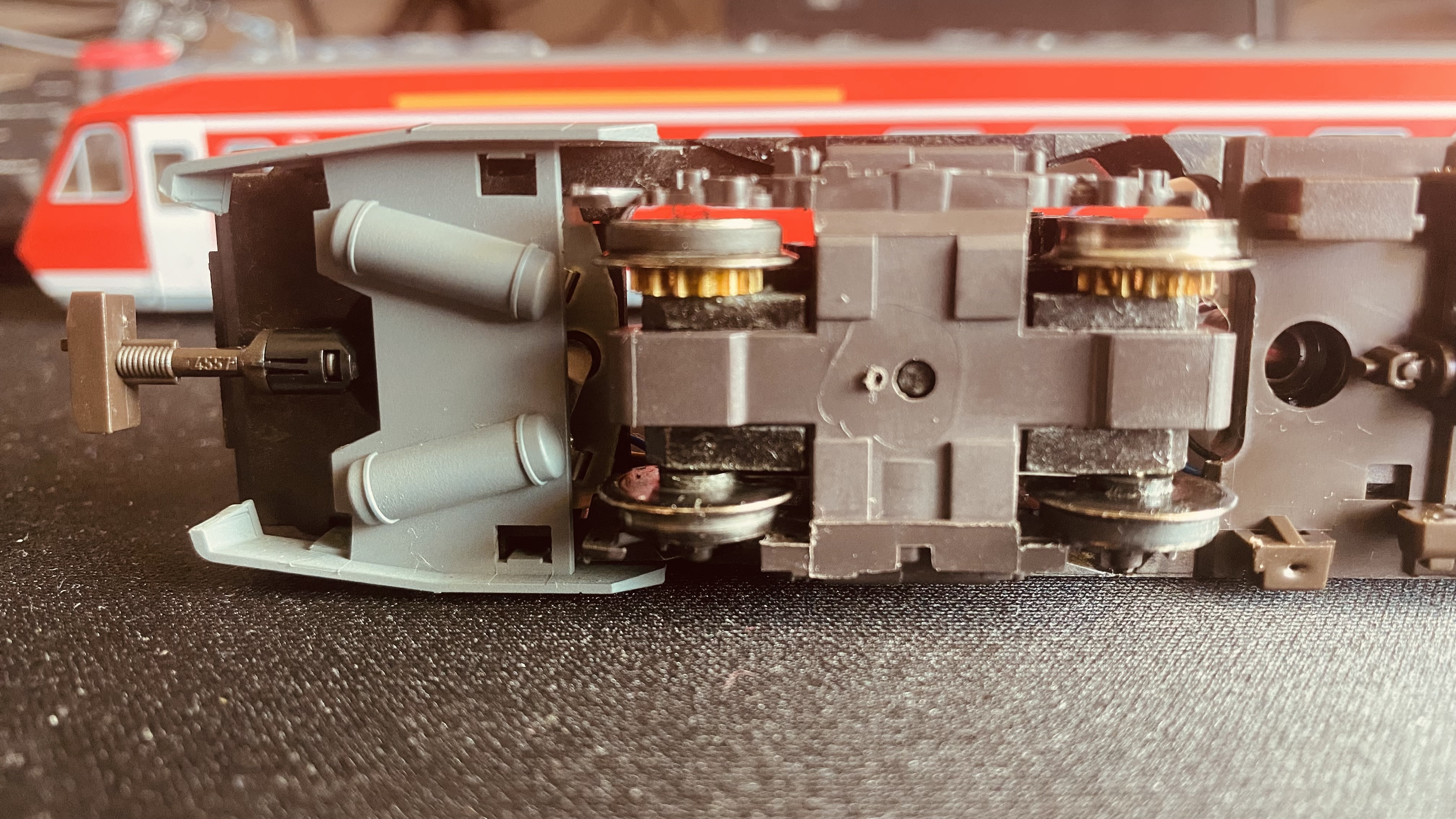
In the photos of the motor, the wire colours can be seen to be different from the DCC standard. They correspond to Fleischmann's FMZ norm, not DCC. Therefore, blue and black are the rail connections, red and violet the motor connections (with blue also being the common return), and the light/dark brown wires are the + for the lights. The small PCB visible on the left is the handoff point for the decoder, which actually uses the DCC colour scheme.
The photo also shows something that looks like a resistor, between the violet wire and the motor. Research has revealed that this is not a resistor, but a choke coil which serves to suppress electromagnetic interference from the motor. These parts can sometimes cause issues with digital operation. I was also told that there should be one of these coils on each motor connection, but there is only one in mine. If I look closely at the connection of the lower red wire on the motor shield, it seems like something might have been de- and resoldered there. I'll probably never know for sure.
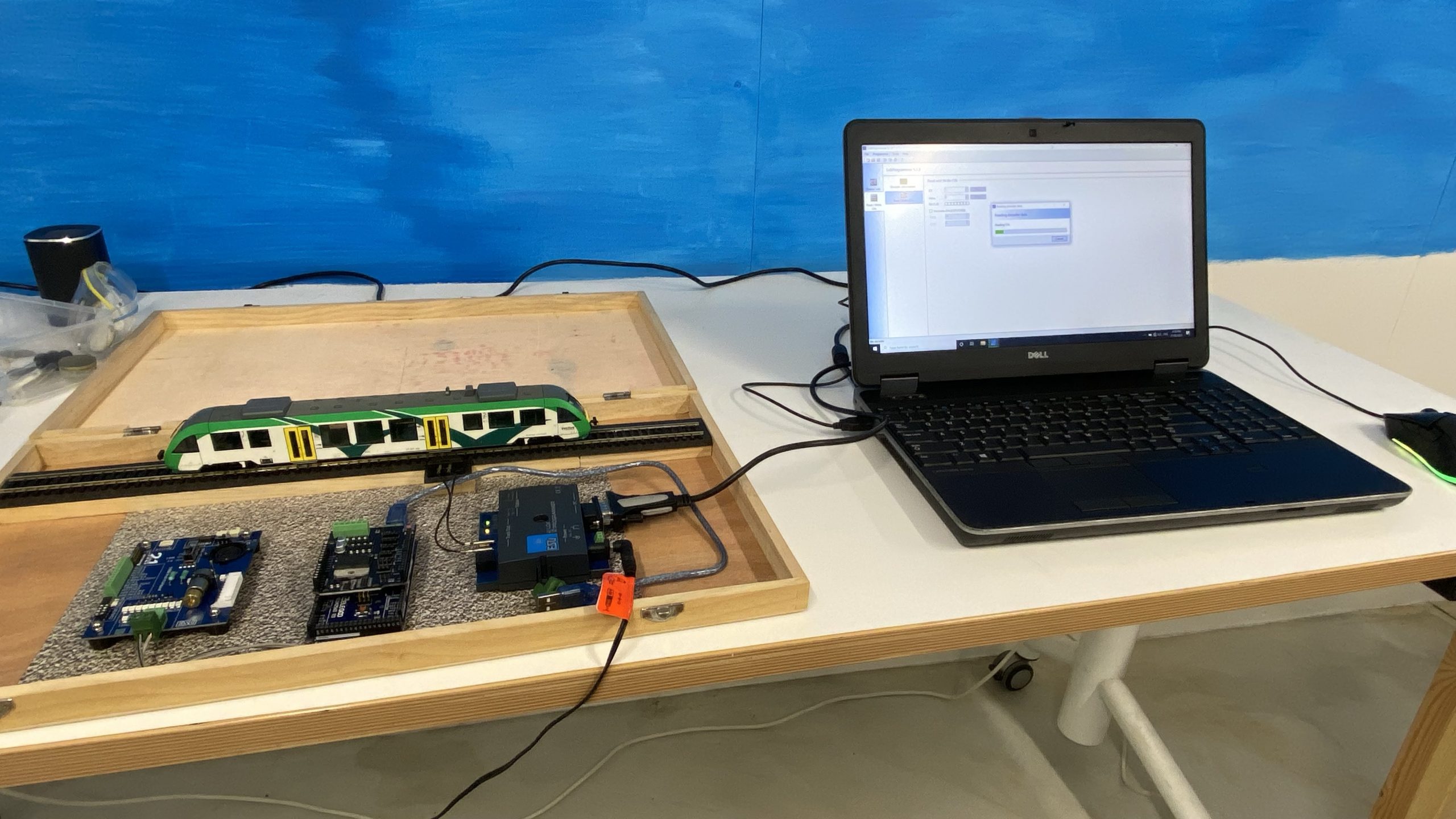
By fluke, I figured out why the model wasn't responding at all to commands from my ECoS central: RailCom. Apparently, some older decoders don't like the RailCom cutout in the digital signal. The moment I turned off RailCom in my ECoS, the model responded.
That's not a solution though - I like RailCom and RailCom+. It makes my life easier. So a decoder that has problems with RailCom can't stay. My next step with this model is therefore to replace the decoder. I'm also contemplating to install an 8-pin plug instead of hardwiring the decoder into the model. It may take me some time to acquire the necessary bits, and the next episode of Project Pendolino will cover the decoder change and its results. The lights will be a topic for later - I'll focus on running optimisation first.