Truth be told… the Mk1 of the programming box was always more of a proof-of-concept than an actually usable thing. It was used once or twice, but was so unwieldy that it really needed improvement. I had a few things in mind for making this contraption better, but my main pain point were the wires. They just had to be concealed somehow, everything else was just too ugly.
Initial attempts at creating a raised cover for the wires in the existing box were not successful. The box is just too flat to do anything meaningful, the space constraints meant that there was not enough room for the switches and connectors, and I even ended up breaking a few things. I contemplated getting a different box with the appropriate dimensions, but it wasn’t a high priority, and with a slim budget there was always something else that was more urgently needed. So I kept putting off the improvements, while not using the box at all.
Until I came across another wooden box of the same kind.
Having two of those boxes gave me an idea. What if I could turn two into one? I initially thought about dismantling and reassembling the two boxes into one deeper box, in which I could then create an intermediate layer. But ultimately that seemed too complicated. I settled on a variant where I simply bolted both boxes together to form a double-lidded box. The top part contained the devices and test track as before, the bottom part was used to conceal the wires.
As for the wiring, I also moved away from my original idea of using plugs and sockets to create the required connection between programming devices, track, or decoder tester. What I started envisioning over time was this: I wanted to be able to plug power into the box, then switch on the combination of devices required for the specific task, put the loco or decoder on the track or tester, and perform the work. Power-wise, this was not a problem, because the Arduino motorshield can be powered from the same power supply as the LokProgrammer (the Arduino itself still needs USB power). My biggest concern with this setup was the remote possibility of accidentally creating a power loop and frying an expensive device.
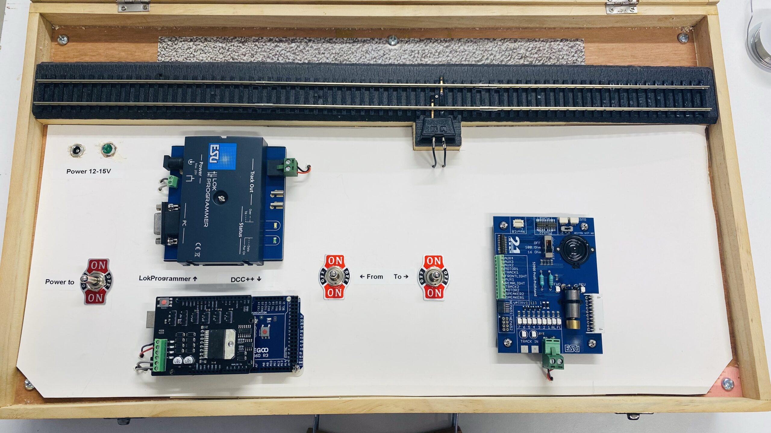
I acquired three DPDT switches with a centre-off position. These switches are quite big and heavy. I also added a power jack matching the ESU power supply, and a LED to indicate that the box has power. The power jack is wired into the centre position of the leftmost switch, LokProgrammer and Arduino each into one of the On positions. The middle switch is the track-out, with both devices again wired into one of the On positions, and a set of wires going across to the third switch, which is also wired into the track and the decoder tester. I verified the correct power flow using a small lightbulb with a wired socket – a great little tool to have around for all kinds of quick tests. These bulbs are used for lighting up model buildings and are specified for 12-16V.
Once I was happy with the switches and wiring, I connected up all the devices and tested carefully. Everything worked as expected, which surprised even me. Now I have an easy way to program and test new decoders and locomotives, it’s quick to set up and pleasant to use. I still have to connect each device to USB individually, but that’s not a big worry. On the Arduino Motorshield, I only have the programming output wired into the track-out. If I need to test something on this device, I can send the command “<1 JOIN>” to make it temporarily provide main power on the programming output. That helpful advice given to me by someone on a German model railway forum saved me from wiring in yet another switch.
Overall, I am quite happy with Mk2 of this project.